Week 4 (1/30 to 2/4)
Assembly
1/30 - Monday
Robot Cart
We finalized our BOM for Robot Cart and finished ASM drawings.
Finished Drawings but still need it to get approved
Started Measuring Wood (Preparing to cut)
Pneumatics
Set all regulators to 60 psi
Helped test claw iteration with pneumatic test bench
Tested Solenoids
Did Training on regulators
We continued to work on the new bumpers.
We attached the pool noodles to the wooden base
Laid out the fabric and began to staple it in place
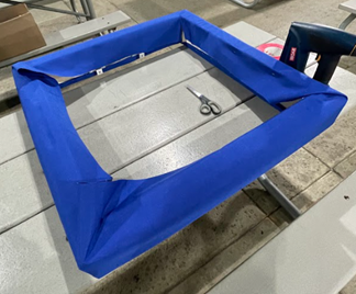
Bumpers with fabric set up.
2/3-Friday
Robot Cart
We started measuring and cutting wood for Robot Cart
We rediscussed with our advisor and decided to redesign our robot cart (table portion) using Milwaukees for storage
Arm and Claw
We adjusted the regulators on both the arm and the claw
We tested the next iteration of the claw
Pneumatics
We tested solenoids
Intake
We finished mounting the intake onto the robot
Bumpers
We readjusted the holes for C-channels and reattached the C-channels, pool noodles, and fabric
We finished the swerve bumpers and tested them on the actual swerve
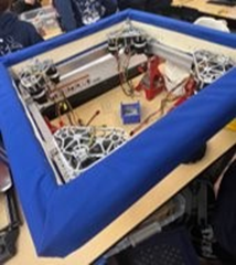
Bumpers on the actual swerve.
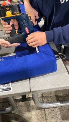
Members using the staple gun to attach fabric to bumpers.
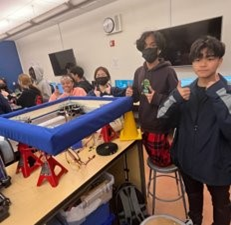
Members working on the bumpers.
Swerve
We removed the crossbeams from the swerve drive base.
2/4-Saturday
Robot Cart
We adjusted the table height with the Milwaukees
We finished the CAD of the robot cart
We cut the upper support bars for the cart
We added to the Robot Cart BOM
We decided on custom décor ideas to add to the cart
Cone runner
We added the electrical connections to the cone runner
Pneumatics
We switched the pneumatics on the prototype robot
Bumpers
We attached the numbers to the bumpers
Repacking
We remade the mechanical list and double-checked the electrical packing list
CAD
Elevator Group
We Continued to work on the write up/ procedures for the Elevator assembly. This guide serves as a manual for assembly and a way to increase the ease of Assembly and speed up the overall assembly process.
We realized that we might not have enough spacers for the elevator. After getting the number of spacers we need for the elevator, we counted the ones we have. We decided to 3D print the spacers necessary.
Buddy Climb
We worked on finalizing the Buddy climb CAD and drawings. The Buddy climber drawings got checked during this meeting by Kloe and James Cozatt.
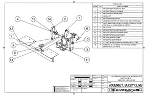
Buddy climb drawing
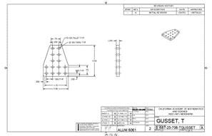
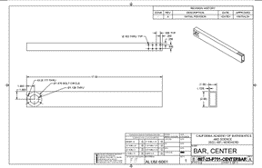
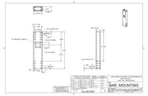
We added accessibility windows to the horizontal bar that allows us to screw in the polycarbonate onto the bar from the side.
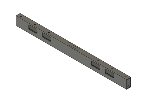
CAD of the horizontal bar
Battery Plate Group
We realized we needed to CAD a new battery plate because the side did not fit as we were making the gap between the two bars from 7 inches to 11 inches. We decided to have a place for battery as long as the compressor.
The CAD of battery plate has been finalized. Drawings of Battery Plate have been finished and are ready for approval.
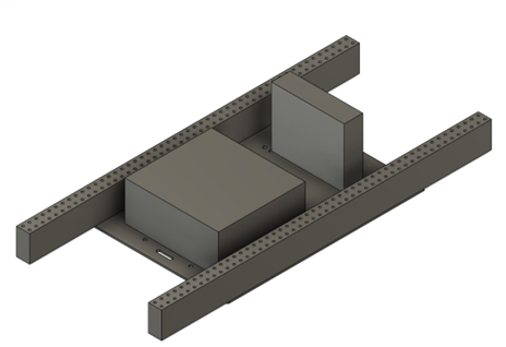
CAD of the Battery Plate
Side Notes
1/30/23
Joyce:
We fixed some gussets and changed the diagonal bar because there was too little space for the batteries. We also did some drawings.
Kloe:
We adjusted the angles and wheel positions of rotational claw. We created a parts list for Linear claw and then we Lasercut all the Polycarbonate parts. Finished the drawings for West Coast bumpers.
2/3/23
Joyce:
We helped assembly with robot Cart. We also discussed with Assembly about what they believed that the ideal table cart height should be. To reach 41 inches, we decided to ad 2x4s to the bottom.
Kloe:
We completed the Linear Claw Assembly and tested the Linear claw.
Joyce:
Worked on motor mount placement, cad, and drawings. Helped assembly with electrical placement. Assisted navx cover prints
Manufacturing
1/30
Our mini mill was prepped to manufacture gussets, but it was decided that the CADs would be redone. Instead, we bandsawed polycarbonate parts for CAD prototypes.
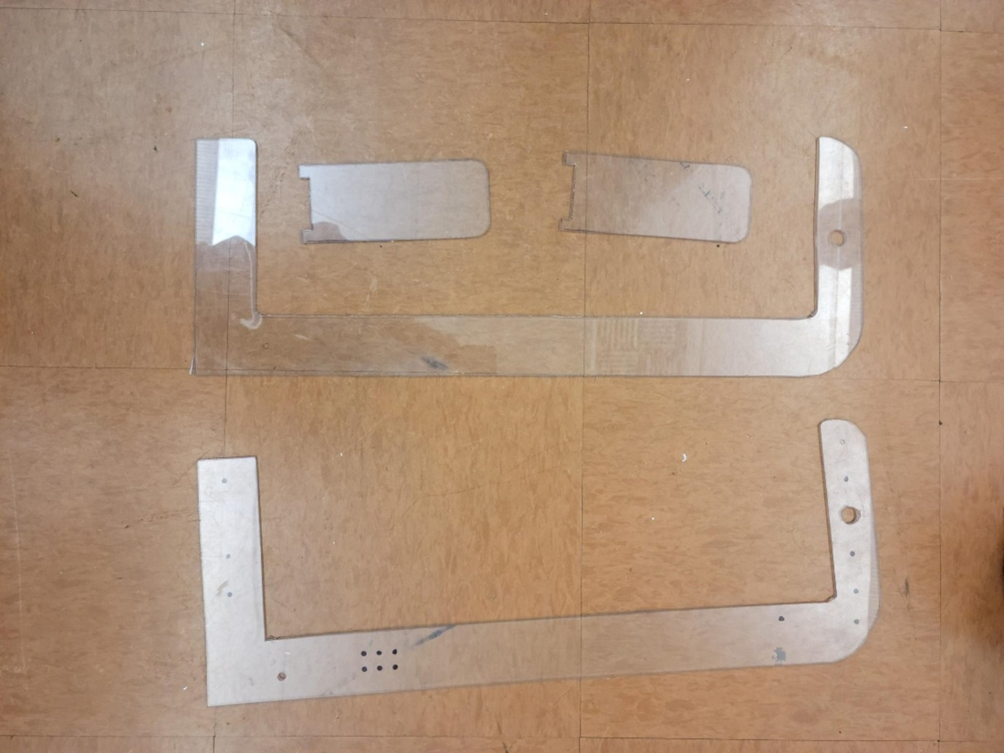
The polycarbonate parts
2/2
On Friday, we finished facing all the stock for the bars, and manufactured the bud gussets.
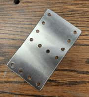
The bud gussets
2/3
A gusset plate that was previously manufactured for RL elevator was band sawed, sanded, buffered, and deburred due to the reaming program being too shallow. Afterwards, another plate of gussets (1.5x1 gusset and top gusset) for pivoter were made, bandsawed, and sanded, but not yet buffered or chamfered. Furthermore, the studs, crossbeam (swerve drive), and crossbar for the pivoter frame was completed. For the remainder of the meeting, we cleaned up the machine shop and cleaned the chips from the machines.
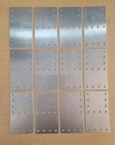
The bud gussets
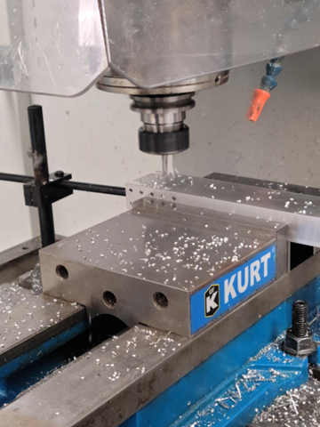
The milling machine
Programming
Vision Group
We changed the driveToTarget command to be able to drive to any type of object(Cube, Cone, Tape, Tag) and we made new sequentialcommandgroups. We made one for getting an object and one for scoring an object.
public class CommandsThatImplementDriveToTarget {
    public class getGameObj extends SequentialCommandGroup{
        public getGameObj(SwerveDrivetrain drivetrain, Limelight limelight, Arm arm, Claw claw, PipelineType pipeline){
            addCommands(
                claw.clawOpen(),
                arm.moveArmScore(),
                new ApproachCombined(drivetrain, limelight, 2, pipeline),
                arm.armExtend(),
                claw.clawClose(),
                arm.armStow()
            );
        }
    }
    public class scoreObj extends SequentialCommandGroup{
        public scoreObj(SwerveDrivetrain drivetrain, Limelight limelight, Arm arm, Claw claw){
            addCommands(
                arm.moveArmScore(),
                new ApproachCombined(drivetrain, limelight, 2, PipelineType.TAPE),
                arm.armExtend(),
                claw.clawOpen(),
                arm.armStow()
            );
        }
    }
}
We also created a class for the AirCompressor as it is used in several subsystems and has an analog output to be logged.
public class AirCompressor extends SubsystemBase implements Reportable {
    private Compressor compressor;

    // Pressure sensor is connected to analog port on RoboRIO
    private AnalogInput pressureSensor = new AnalogInput(PneumaticsConstants.kPressureSensorPort);

    public AirCompressor() {
        compressor = new Compressor(PneumaticsConstants.kPCMPort, PneumaticsModuleType.CTREPCM);
        compressor.enableDigital();
        // compressor.disable();
    }

    @Override
    public void periodic() {}

    public void reportToSmartDashboard() {
        SmartDashboard.putNumber("Air Pressure", pressureSensor.getValue());
    }
}
Subsystems Group
We worked on two different versions of position control for the arm.
The first one is through pure PID control using the PIDController class and brake mode to compensate for the gravitational pull.
public void moveArm(double position) {
    armPID.setSetpoint(position);
    double speed = armPID.calculate(rotatingArm.getSelectedSensorPosition(), position);
    if (speed > 3000) {
        speed = 3000;
    } else if (speed < -3000) {
        speed = -3000;
    }
    rotatingArm.set(ControlMode.Velocity, speed);
    if (armPID.atSetpoint()) {
        rotatingArm.setNeutralMode(NeutralMode.Brake);
    } else {
        rotatingArm.setNeutralMode(NeutralMode.Coast);
    }
}
The second method is through motion magic.
public void moveArmMotionMagic(int position) {
    // config tuning params in slot 0
    rotatingArm.set(ControlMode.MotionMagic, position, DemandType.ArbitraryFeedForward, Math.cos(position * ArmConstants.kAnglePerTicks)*ArmConstants.kArbitraryFF);
    this.targetTicks = position;
}
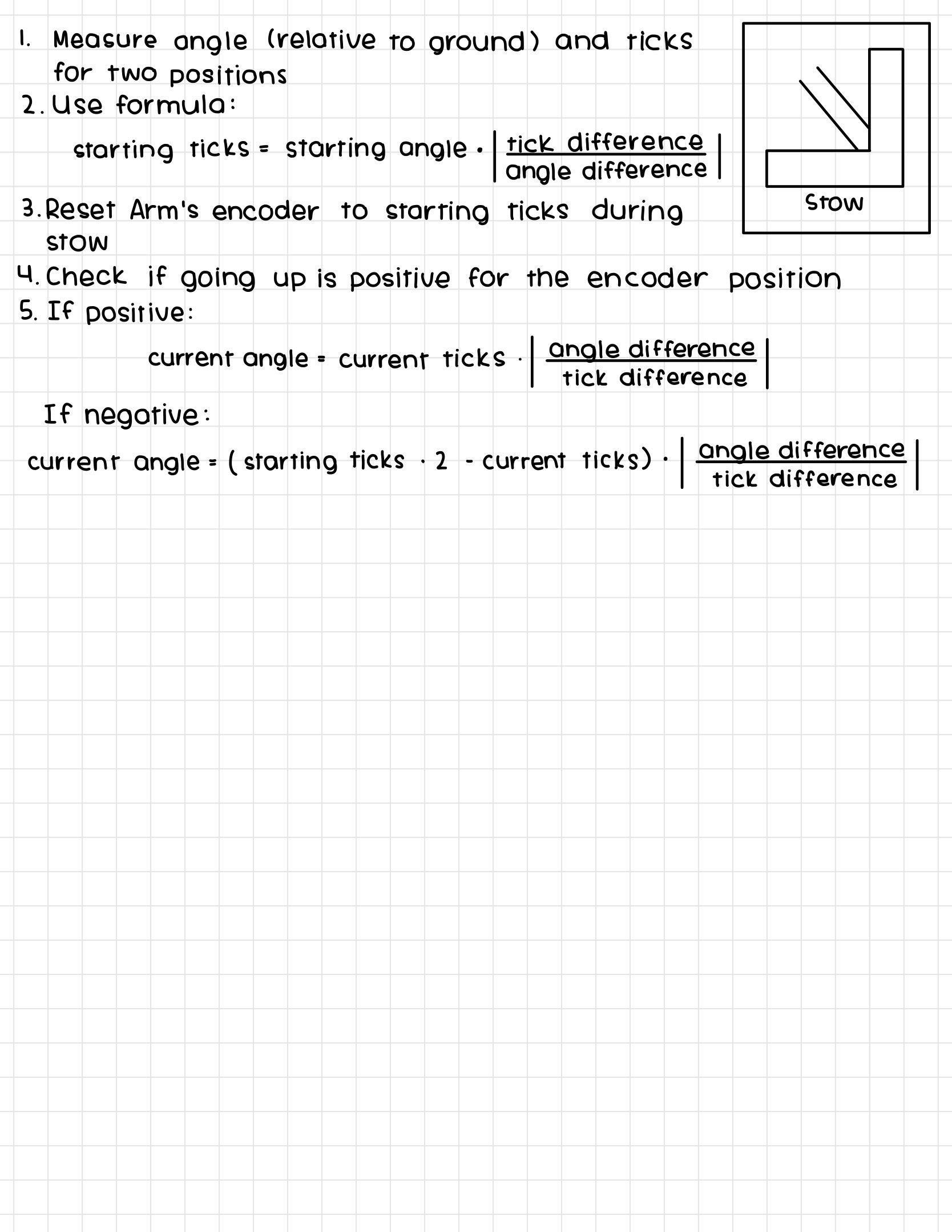
For the motion magic method, it was necessary for us to figure out how to find the current angle.
Swerve Group
This week, we worked on maintaining our codebase. We merged most of the branches in our Github repository into our development branch, and then merged the development branch into the main branch. We then created a release of our code. Afterwards, we deleted all of our unused branches.
After the release, we worked on minor refactoring changes, such as moving default command assignments to their own methods and centralizing our SmartDashboard calls. To enforce the implementation of the reportToSmartDashboard() method in our subsystems, we created the interface Reportable and implemented it in all of the subsystems.
The reportable interface:
package frc.robot.subsystems;

public interface Reportable {
    public void reportToSmartDashboard();
}
Our new, centralized reportAllToSmartDashboard() method:
public void reportAllToSmartDashboard() {
    // SmartDashboard.putNumber("Timestamp", WPIUtilJNI.now());
    imu.reportToSmartDashboard();
    claw.reportToSmartDashboard();
    arm.reportToSmartDashboard();
    coneRunner.reportToSmartDashboard();
    if (IsSwerveDrive) {
        swerveDrive.reportToSmartDashboard();
        swerveDrive.reportModulesToSmartDashboard();
    } else {
        tankDrive.reportToSmartDashboard();
    }
    airCompressor.reportToSmartDashboard();
}
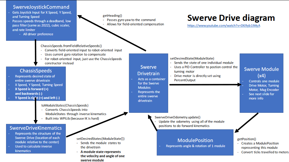
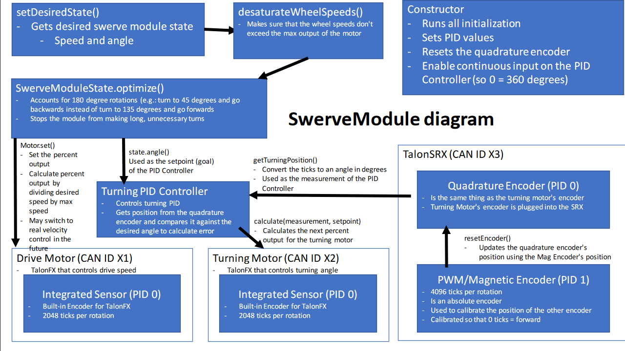
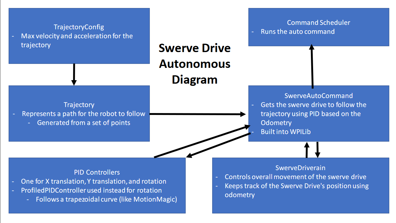
We also created diagrams on how our implementation of Swerve Drive works, in order to document it for the rest of our subteam.
